Electrical
The circuits that connect it all together!
Electrical Diagram
Electrical layout
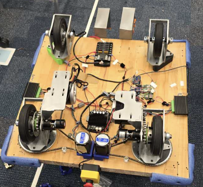
The electrical system originally began with three voltages: 24V, 12V, and 5V. We later simplified the design after realizing the 12V rail was unnecessary because we were no longer using the 12V lidar. All high-power components could run directly from the 24V battery, and the low-power devices did not require a dedicated 5V supply. Instead, we used a high-wattage power bank, which provided an integrated BMS and safely powered the Raspberry Pi, USB camera, and UWB modules. This reduced complexity and increased system safety.
- 24V system: Breakers were sized slightly above the continuous current draw of each motor.
- 5V system: All 5V devices were powered through the Raspberry Pi, which was connected to a high-wattage power bank.
- Mounting: 3D printed C-clamps secured the electrical system to the underside of the cart.
- Power distribution: Wago connectors were used on power lines to make it easy to isolate and test individual components.
- Data lines: Soldered connections were used because communication signals are more sensitive and require reliable joints.
- Prototyping: We transitioned from solderless breadboards to soldered boards to improve robustness during testing.
- Cable management: Velcro zip ties were used to organize and bundle wiring.
Challenges
Emergency stop did not fully cut power
The Problem: We did not realize that the GPIO ground on the drive controller was shared with the controller's main power ground. Our emergency stop only disconnected part of the system, which caused unsafe behavior and resulted in the robot hitting a wall.
The Solution: We redesigned the grounding so there was only one ground connection. This ensured that activating the emergency stop fully disconnected both power and ground, shutting down the entire drive system safely.
Wires unplugging during testing
The Problem: Wires on the Raspberry Pi and breadboard would frequently come loose while the robot was running. This made it difficult to tell whether problems were caused by software bugs or electrical failures.
The Solution: We secured critical connections using hot glue and reduced movement in the wiring. This made the system far more stable and eliminated many false software debugging sessions.
Hard to debug electronics versus software issues
The Problem: Our early setup used solderless breadboards and unlabeled wires, which made it unclear whether failures were caused by bad code or poor electrical connections.
The Solution: We created a clear step by step debugging procedure and relied on a multimeter to check voltages and signals directly instead of guessing based on code behavior alone.
Unclear wiring and poor organization
The Problem: As the system grew, it became hard to tell which wire connected to which component. Tracing wires took a lot of time and increased the risk of mistakes.
The Solution: We labeled every wire, created a clear electrical diagram with defined pin inputs and outputs, and zip tied and mounted wires to the board to keep them organized and away from moving parts like the wheels.