Overview
Project objectives, system diagrams, and design process
Mechanical
- Design a system that is able to drive with a heavy load of 200lbs
- Create an ecosystem with ease of programming in mind
- Drive uninterrupted for long periods of time (>30mins)
Electrical
- Robust wiring and soldering
- Create modular parts for easy testing and debugging
- Design clear electrical diagrams that are easily understood by others
Software
- Support both manual and autonomous operations
- Prioritize safety and fault tolerance
- Be modular, reliable, and easy to extend
System Overview
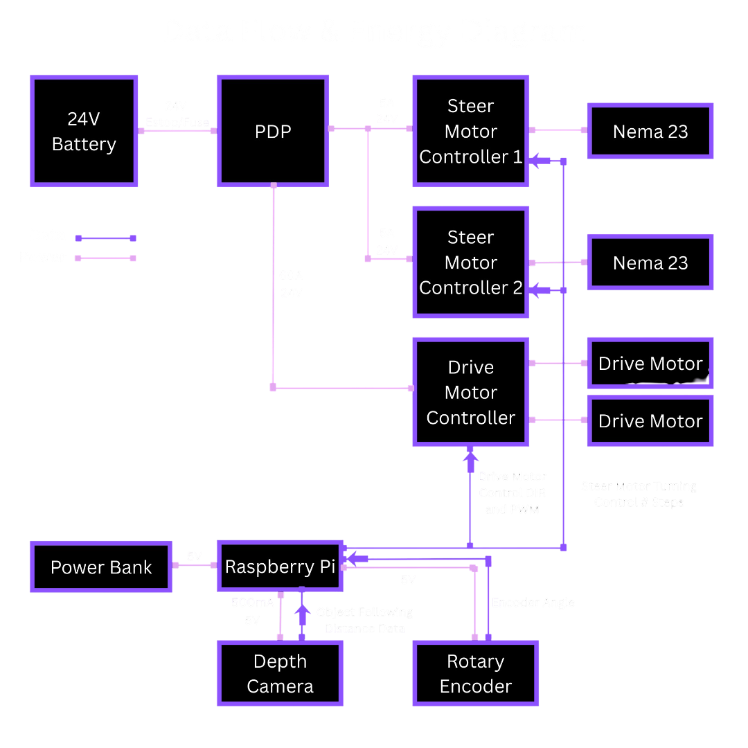
System Diagram
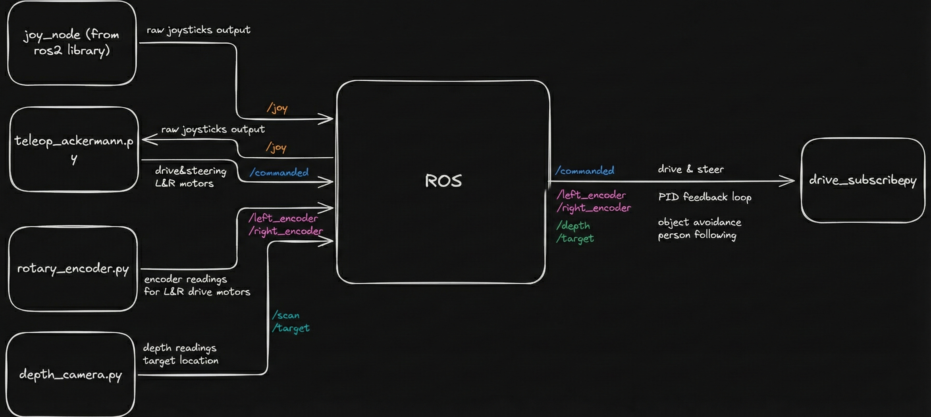
Data Flow & Energy Diagram
Design Process
Our design process felt like a sprint up a steep hill. We knew from the start that even our Minimum Viable Product (MVP) was pushing it, so the only way to make progress was to move quickly, test ideas often, and follow whatever paths created the least friction. We got each subsystem working on its own first, almost like scattered puzzle pieces, and then slowly brought them together into a single system. There were plenty of moments when we disagreed about the final design and couldn't settle on one direction, but each time we returned to the MVP to figure out what was truly necessary. If something didn't help us reach that minimal goal, we let it go.
Money pushed us to be creative too. Even after adding some of our own funds, we still couldn't afford certain parts like a LiDAR. We borrowed one, struggled with its integration with our cart, and were eventually lucky enough to borrow a depth camera from another team that better suited our needs.
Key Design Decisions
Why ROS?
We chose ROS 2 as the core software framework because it provides a robust, scalable foundation for robotics development while remaining fully open-source. ROS 2 naturally supports a publisher–subscriber architecture, which allows sensors, controllers, and behaviors to run as independent nodes that communicate through well-defined topics. Using ROS 2 gave us several key advantages: Modularity: Each subsystem (vision, motor control, joystick input, safety checks) runs as its own node, making debugging and iteration much easier. Collaboration & Parallel Development: Multiple developers can work on separate nodes without interfering with each other. Networking Support: ROS 2 allows seamless communication between the Raspberry Pi on the robot and a development laptop over a network, enabling remote monitoring, debugging, and visualization. Simulation & Visualization: Built-in support for tools like RViz and Gazebo allows us to visualize sensor data and robot behavior before deploying changes to hardware. Scalability: The same software structure can scale from simple teleoperation to fully autonomous behavior without major redesign. The Raspberry Pi 4B runs the full ROS 2 stack and serves as the central compute unit, handling sensor input, control logic, and actuator commands.
Why Front Wheel Swerve Drive?
We chose to implement a front wheel swerve drive because it provides a highly mobile, technically challenging drivetrain. While we could have chosen to do front wheel steering with rear wheel drive, it would have caused lower maneuverability and difficulty retaining traction. A swerve drive also allows us to perform steering with Ackermann in mind. Ackermann is a characteristic in which one wheel steers less than the other, which helps improve maneuverability and reduces slippage. Having both drive and steer in the front also posed an exciting challenge to us for packaging and integration. It forced us to design mindfully and caused some unforeseen challenges later on that made us rethink a lot of parts.
Why Depth Camera?
We chose a depth camera over a 360-degree LiDAR because we couldn't find a good way to mount the LiDAR where it could actually see everything around the cart. The best we could do was place it in the front, which would have limited it to about 180 degrees of coverage. On top of that, the LiDAR we had access to was older and much harder to work with. It needed PoE and a more complicated setup, while the depth camera (a RealSense) connected cleanly over USB-C and already had a ROS2 integration we could use right away. The existing ROS2 publisher made it simple to get depth data streaming, so the depth camera ended up being the most practical choice for our system.
Why switch from UWB to camera for human following
We originally relied on UWB modules for human-following, but the system struggled in real environments. The estimated position would drift even when the person wasn't moving, and accuracy broke down whenever the robot approached certain angles. Metal components on the robot reflected the UWB signal heavily, and other parts blocked line-of-sight altogether, making the ranging data noisy and unreliable. After extensive calibration, filtering, and controlled testing, the limitations were still too severe for consistent tracking. This led us to pivot to a computer-vision approach using reflective tape, which provides stable, front-facing detection without the environmental interference that plagued UWB.