Mechanical
How we made the frame, mounts, and more!
Swerve Front Wheel Drive System
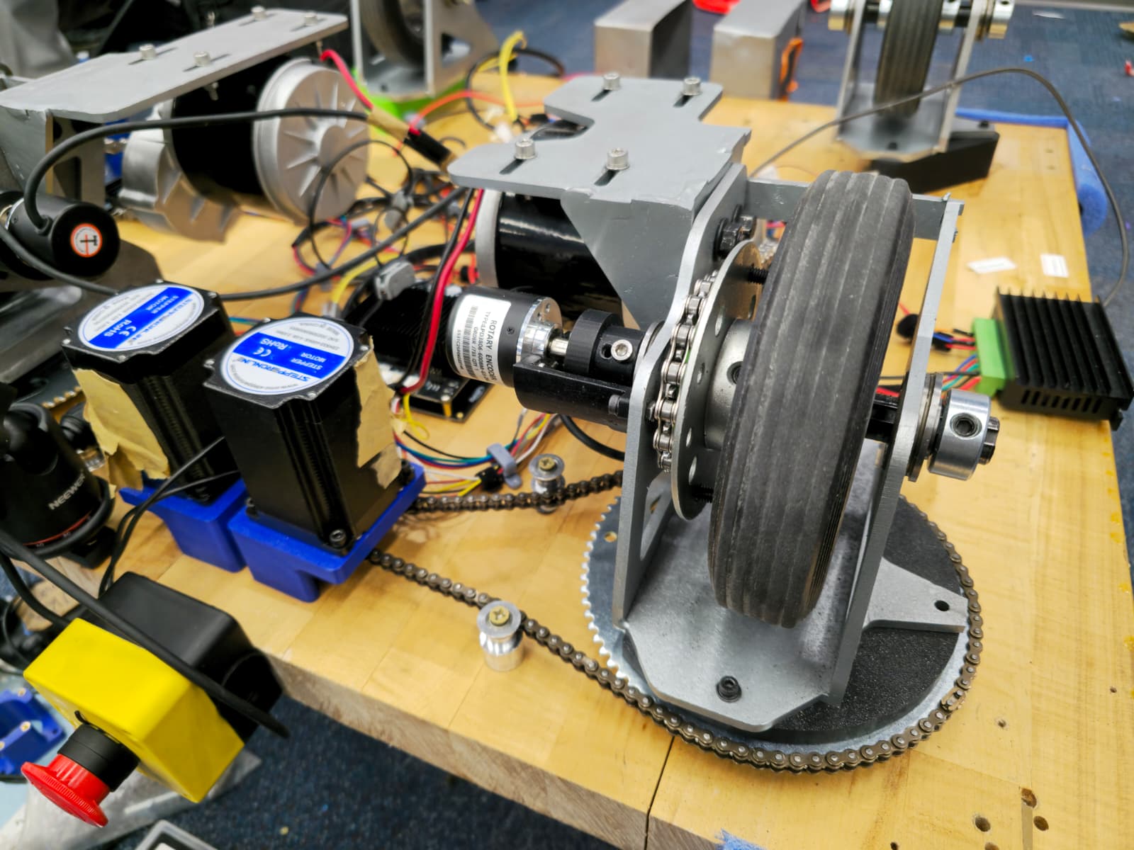
We designed a swerve front wheel drive system for project AURA. The independent steering feature of the two front wheels allows the robot to reach a perfect Ackermann steering geometry, making it turn smoothly with minimal resistance.
Drive System
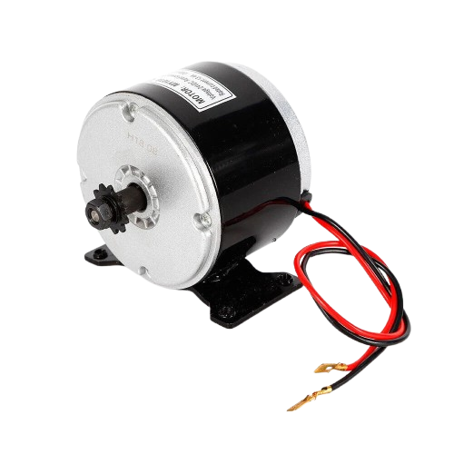
The two wheels are driven by two MY1016Z6 24V DC motors with a sprocket ratio of 9:16. Allowing the robot to accelerate at 1m/s² with 200lbs of load. The two motors are controlled by a PN00218-CYT14 Motor Driver with maximum 30A continuous and 80A peak output.
Power System
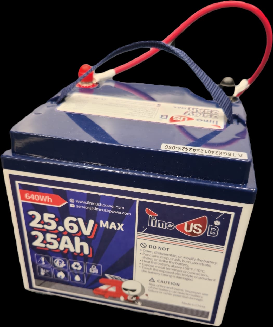
The whole system is powered by a limeUSB 24V 25Ah 2C LiFePO4 battery, allowing the robot to drive for at least 30 minutes with heavy load.
Encoders
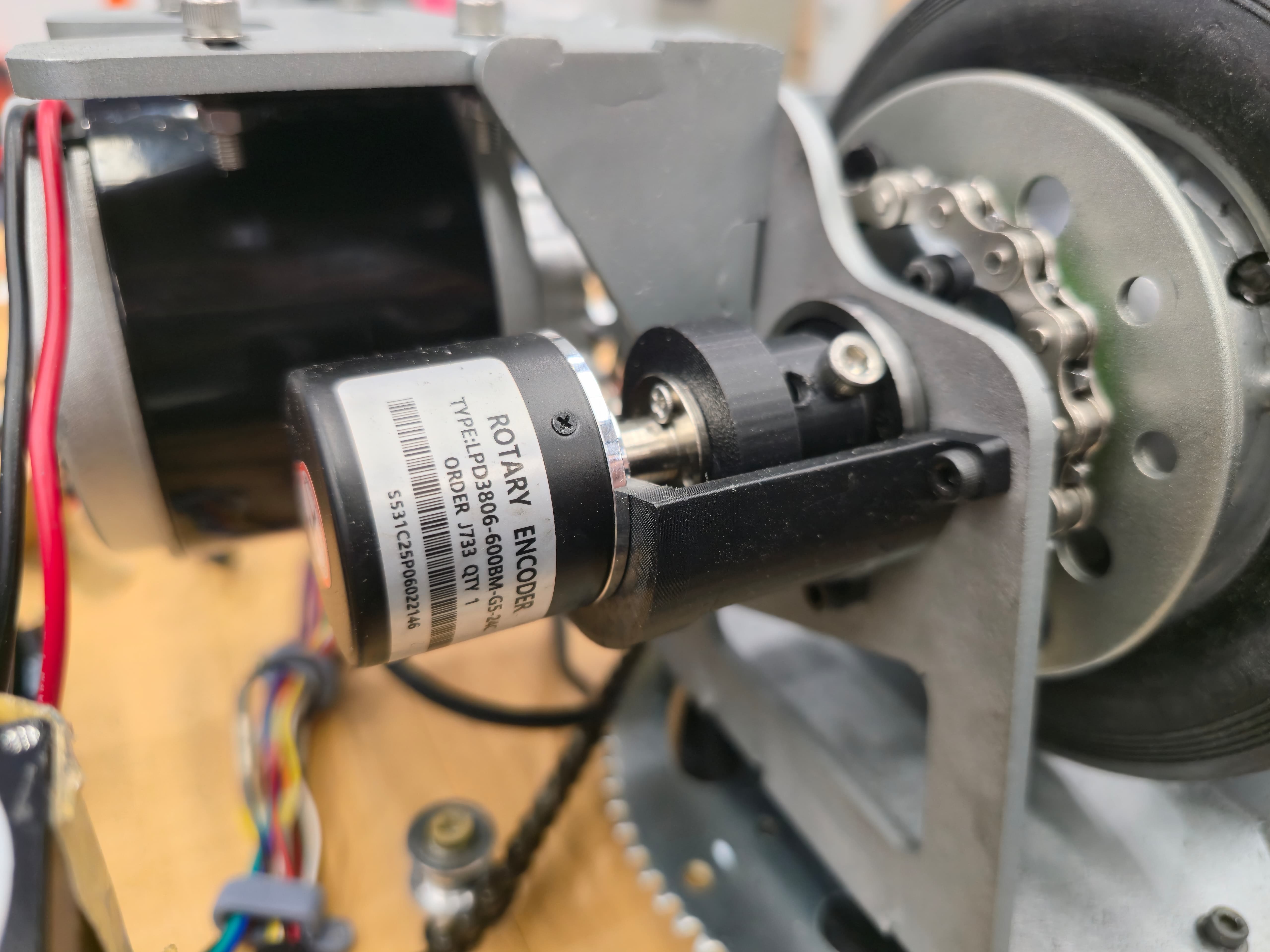
We connected two LPD3806 encoders to the ⅜'' wheel shafts on the front wheels. The two encoders report precise wheel position, allowing us to monitor the speed and displacement of the robot.
Steering System
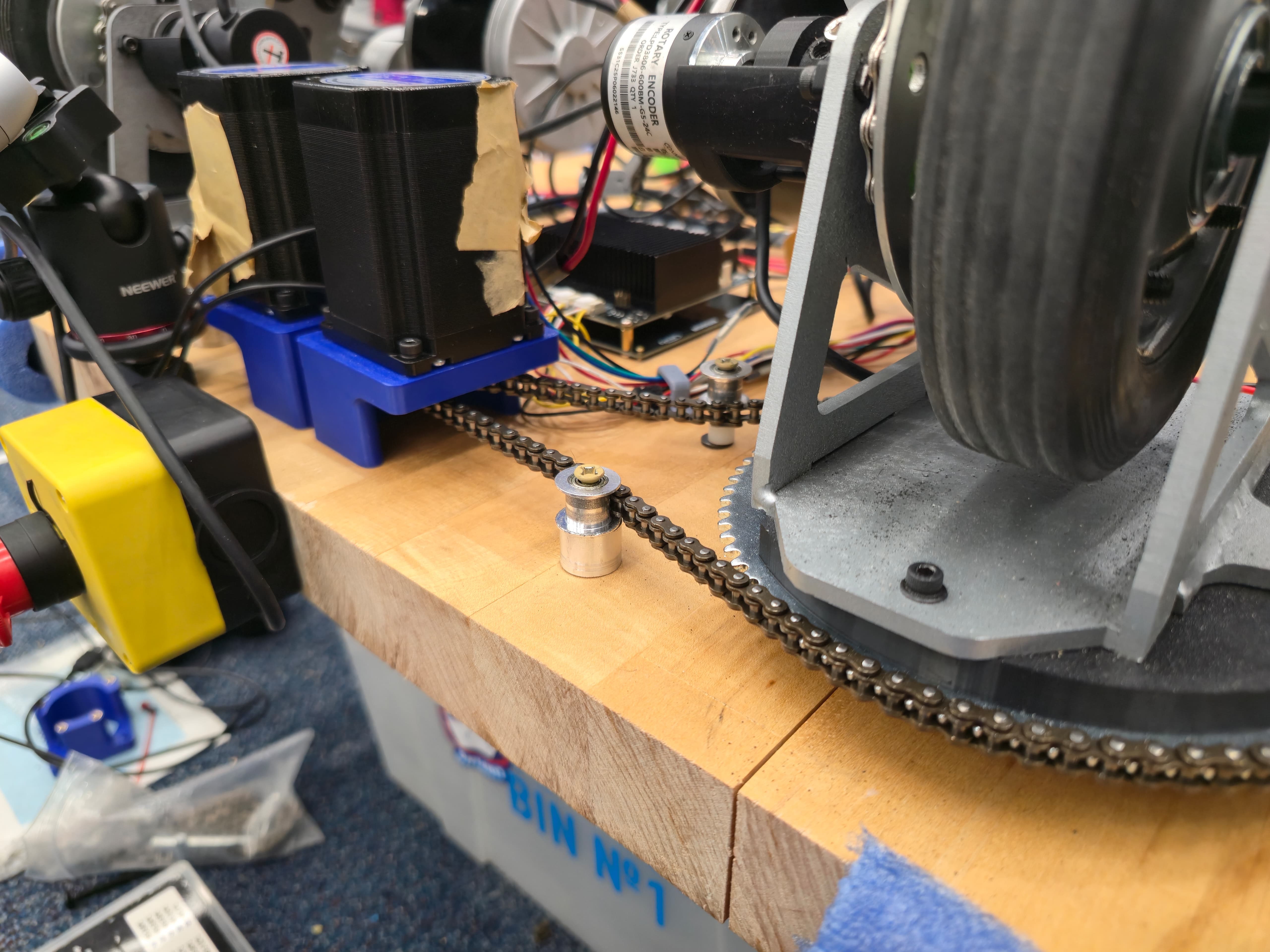
Two Nema 23 2.4Nm steppers steer each wheel independently with a sprocket ratio of 18:80. We use the 18 teeth sprockets as the driving sprocket that is connected to the steppers and the 80 teeth sprockets as the driven sprocket, making sure we have enough torque to steer the robot under 200lbs of load.
Materials & Fabrication
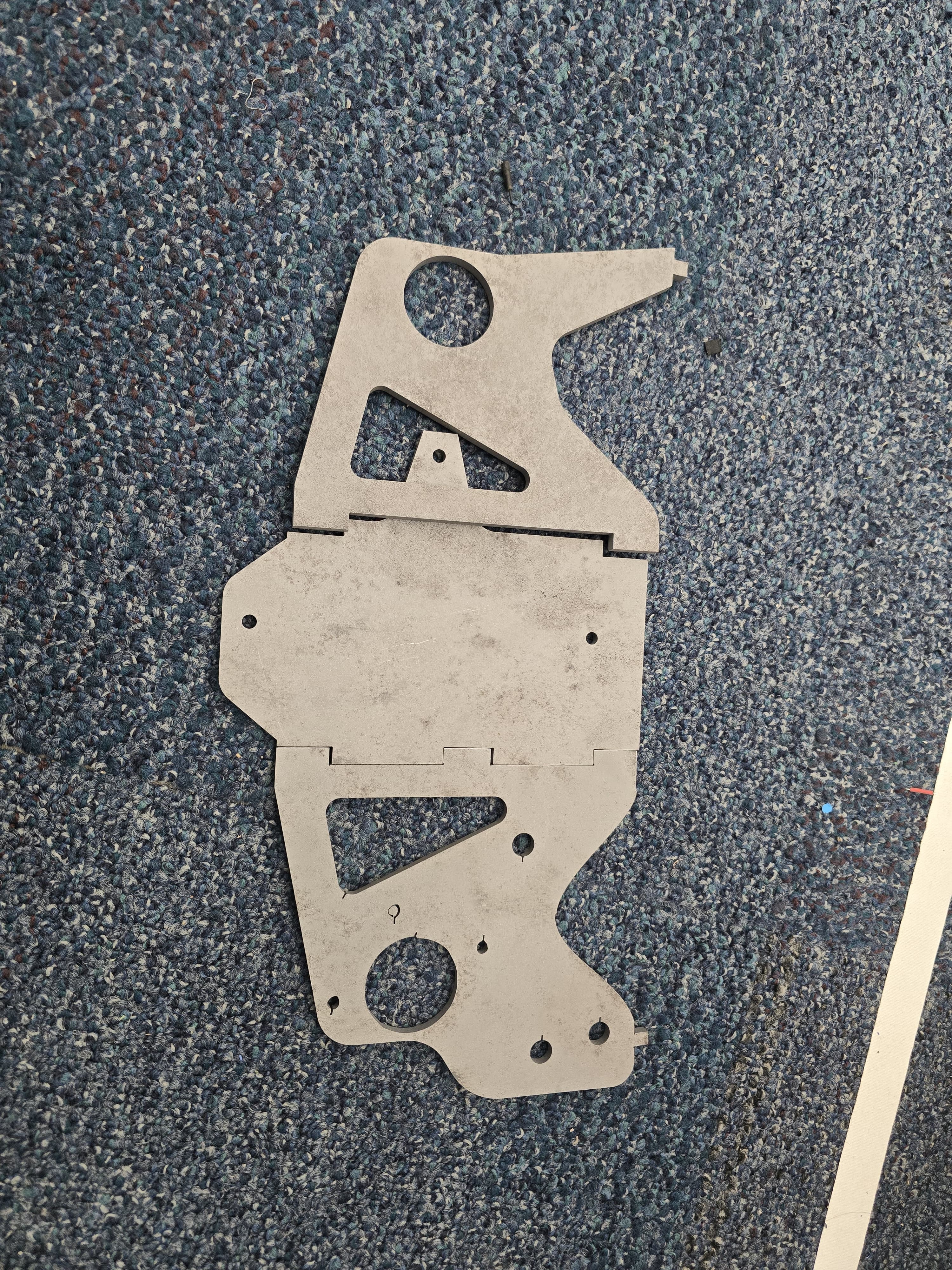
The wheel houses and motor mounts are made from A36 Mild Steel, because A36 steel is easy to fabricate and weld, while keeping the structure strong. We waterjetted the wheel houses and motor mounts from a 0.25'' thick steel plate offered by the shop with an OMAX waterjet. After that, we TIG welded the pieces together and spray painted the pieces to avoid rust.
Wheels
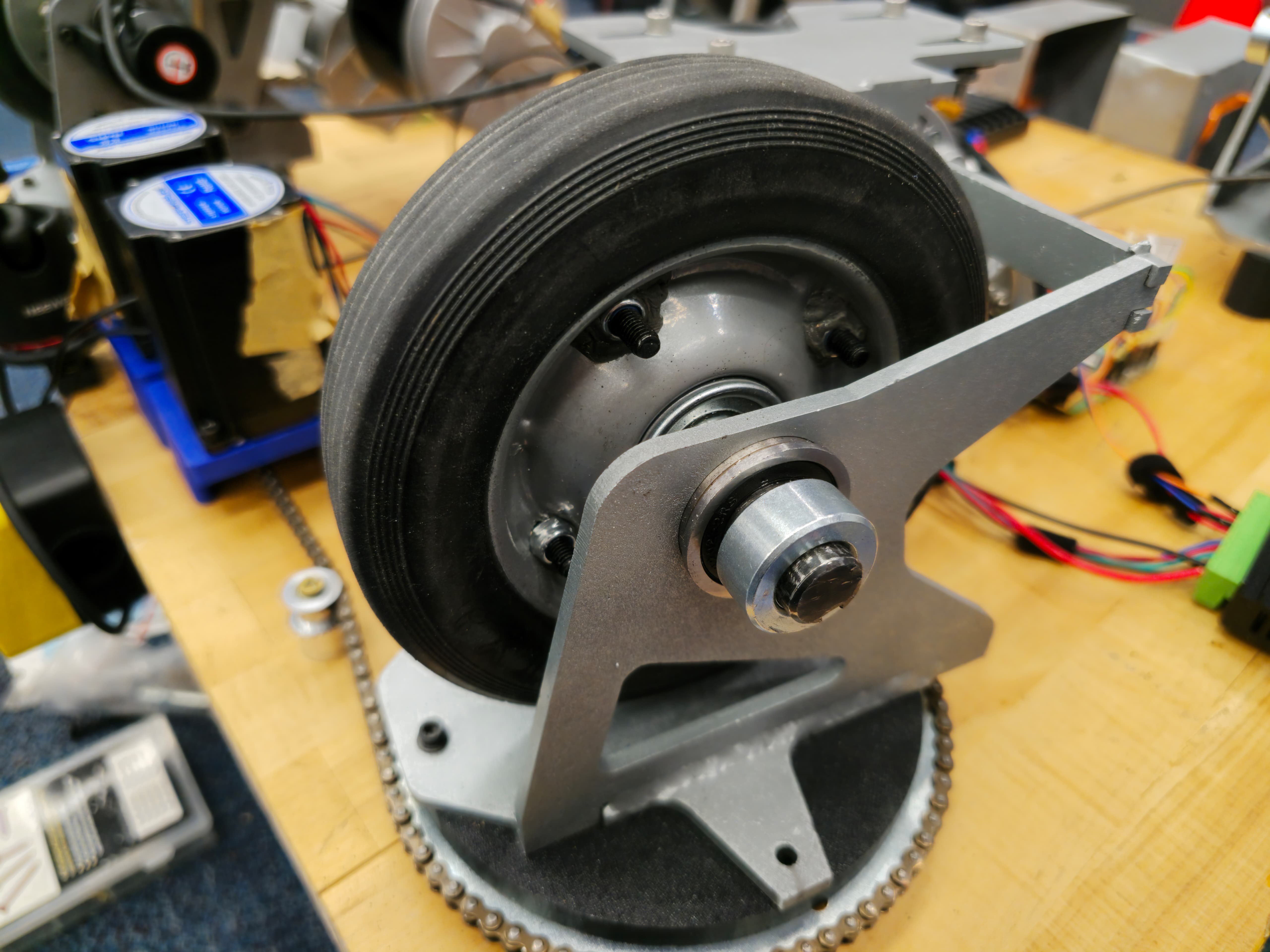
We chose a heavy-duty solid rubber wheel for our robot. The solid rubber wheels eliminated the risk of puncture under heavy load, making our robot safe under intense conditions.
Bearings & Shafts
There are eight heavy-duty bearings in total for Project AURA, two in each wheel. We ran a stress test of putting more than 500lbs of weight on the robot and the bearing survived under the extreme load test. The ⅜'' steel wheel shaft leaves the whole drivetrain with enough redundancy for expected situations.
Challenges
Steering Stepper Mounting
The Problem: Due to the size of the MY1016Z, the mounting of the steering steppers became a problem due to the space constraint on the robot. We initially mounted the steppers to the corners of the robot. However, it turns out to be very unstable and causes chain tensioning issues as the sprockets are too close to each other.
The Solution: We moved the stepper motors to the center of the robot and slightly reduced the maximum steering angle. This allows us to space the sprockets further from each other, giving us enough space to tension the chain without skipping.
Drivetrain Space issue
The Problem: In order to minimize the resistance in steering, we designed the drivetrain to be as compact as possible. The compact size of the drivetrain led to problems with integrating the wheel, the wheel mount, and the wheel sprocket in the tight space without interference. We had trouble with the chain interfering with the bolts and the chain exploded.
The Solution: We tested multiple sprocket spacers and used the thinnest one that doesn't cause interference. We also used shorter bolts for mounting the drivetrain, maximizing the space for rotational components.