System Design
AURA's software architecture is built on ROS 2 (Robot Operating System), using a Publisher–Subscriber (Pub/Sub) pattern to separate sensing, decision-making, and actuation into independent modules.
Each major capability (perception, safety checks, joystick input, and motor control) runs as its own ROS 2 node communicating over well-defined topics. This modular structure allows us to develop and debug subsystems independently while composing them into a complete robot behavior.
In our final configuration, the Raspberry Pi 4B runs ROS 2 as the main onboard computer responsible for real-time motor and sensor control. ROS 2's networking capabilities allow high-level logic to optionally run on a development laptop, with seamless inter-machine communication handled automatically.
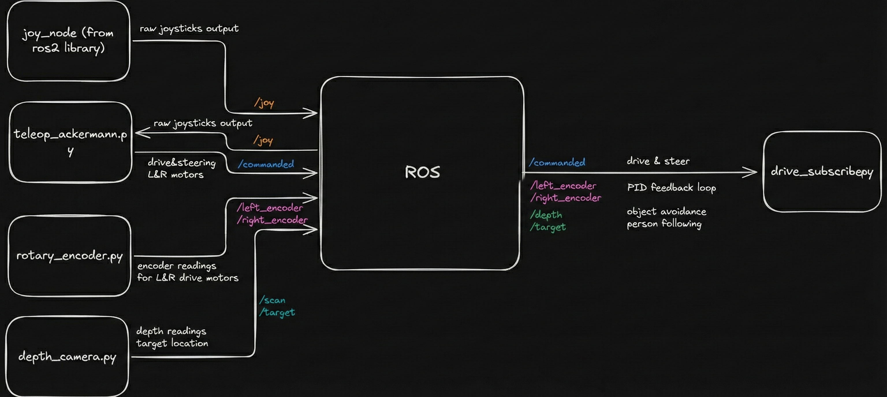
Figure 1: High-level ROS node architecture and data flow.
External Software Dependencies
The AURA software stack is intentionally built from widely used, well-documented tools so that others can reproduce or extend our work:
- Raspberry Pi OS: Base operating system running on a Raspberry Pi 4B.
- ROS 2 (Humble): Robot middleware and communication framework that orchestrates all nodes.
- OpenCV: Image processing and tracking, including thresholding, contour detection, and filtering.
- pyrealsense2: Interface to the Intel RealSense depth camera for synchronized RGB, depth, and IR streams.
Together these dependencies give us a flexible platform capable of real-time control on the Pi while still supporting remote computation and visualization on a laptop when needed.
Depth Camera: Tracking & Safety
Reflective Target Tracking Pipeline
The robot uses an Intel RealSense depth camera both for human
tracking and collision avoidance. A custom ROS 2 node, written
in Python, interfaces with the camera using
pyrealsense2 and processes frames with OpenCV.
To keep the tracking system robust and lightweight, we used a reflective tracking approach: a traffic-cone reflective sleeve was cut into strips and attached to a belt worn by the user. Under the camera’s infrared illumination, this material appears as a bright, easily isolated region without any complex machine learning.
The tracking pipeline:
- Capture synchronized IR + depth frames from the RealSense camera.
- Threshold the IR image to isolate highly reflective regions corresponding to the target belt.
- Apply morphological filtering to remove noise and stitch fragmented blobs.
- Detect contours and filter them by area and distance to reject spurious reflections.
- Fuse with depth data to compute the target’s 3D position relative to the robot.
We use a Kalman filter to smooth noisy measurements and estimate both position and velocity. If the target is temporarily occluded, the filter continues predicting motion for up to ~0.5 seconds (about 15 frames) before declaring the target lost and stopping the robot, avoiding jittery starts and stops.
Obstacle Safety Using /scan
In parallel with tracking, the depth camera publishes a
LaserScan-style message on
/scan by sampling depth along the central row of
the image. This effectively turns the camera into a virtual 2D
lidar for frontal collision checking.
For safety, our ROS 2 safety node enforces:
- Stop zone: If any object is detected within 0.6 m in front of the robot, forward motion is disabled.
- Pause following: Autonomous following is paused while an obstacle is too close.
- Escape only: The robot is only allowed to move backward until the area is clear.
This safety logic is always active and applies to both manual joystick control and autonomous following, providing a consistent safety envelope regardless of mode.
Joystick Control & Safety Interlocks
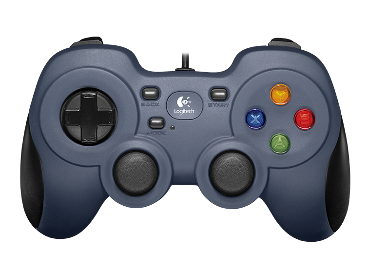
For manual and assisted control we used a
Logitech F310 joystick, connected via the
standard ROS 2 joy package (ros2 run joy joy_node). This publishes joystick state to a topic that our teleop
and autonomy nodes subscribe to.
We designed the mapping to include multiple layers of safety:
- Left stick: Forward and backward linear motion.
- Right stick: In-place turning / steering.
- Right bumper (RB): Must be held for any manual motion; releasing it brings the robot to a stop.
- Left bumper (LB): Must be held to allow autonomous velocity commands to reach the motors.
As a result, the robot cannot move accidentally, and autonomous behavior only runs when the operator deliberately enables it by holding the correct bumper. This interlock pattern proved intuitive for new users and aligned well with our safety goals.
Motor Control & Encoders
Cytron Motor Driver
The robot is driven by a Cytron motor driver controlling two high-power DC motors. Each motor receives:
- A PWM signal that sets the commanded speed.
- A digital direction signal that selects forward or reverse rotation.
The Raspberry Pi generates these signals directly via its GPIO pins. PWM values are computed in software from joystick inputs or autonomous velocity commands, with additional scaling and ramping to limit acceleration and top speed for safety and reliability.
Encoders & Odometry
Each drive wheel is equipped with a relative (incremental) rotary encoder that produces a digital pulse for each tick. The Raspberry Pi counts rising edges on dedicated GPIO pins to estimate:
- Wheel rotational velocity.
- Relative distance traveled.
- Robot odometry for path planning and following behavior.
At low and moderate speeds this approach works well, but at higher speeds we observed missed counts and even occasional decreases in the tick count. This is a limitation of using a non‑real‑time OS and software sampling for high-frequency encoder signals.
Our key takeaway is that accurate high-speed odometry requires hardware interrupts or a dedicated microcontroller (e.g., STM32 or ESP32) or the use of absolute encoders with built-in counting. In this iteration we constrained the robot’s top speed to stay within the Pi’s reliable sampling window.
Manual driving demonstration—motors, Cytron driver, and encoder feedback in action.
Engineering Challenges & Iterations
UWB Localization Failure
The Problem: We attempted to use 4 Ultra-Wideband (UWB) modules to track the user. However, readings were highly inconsistent. We encountered significant signal multipath interference from the metal motor mounts and Non-Line-of-Sight (NLOS) errors, causing the robot to lose the target even within range.
The Pivot: Signal calibration and Kalman filtering were insufficient to solve the hardware interference. We determined that the UWB anchor geometry was too constrained for robust triangulation. We pivoted to a Computer Vision approach using OpenCV, which proved far more reliable for dynamic object tracking.
Encoder Sampling Rate
The Problem: We used simple rotary encoders connected directly to Raspberry Pi GPIO pins. At high speeds, the robot's odometry became irrational—counts would lag or even decrease. We identified this as a hardware limitation: the Raspberry Pi's OS is not real-time, and the CPU could not sample the GPIO pins fast enough to catch every encoder tick.
The Lesson: Software optimization (increasing timer priority) was insufficient. We learned that high-speed odometry requires hardware interrupts or a dedicated microcontroller (like an STM32 or ESP32) to handle tick counting off the main CPU. For this iteration, we optimized our max speed to remain within the Pi's reliable sampling window.
Thread Starvation
The Problem: Our initial code ran in a single loop. Because stepper motors require a specific sequence of "step" signals (High/Low) in a blocking for loop, the steering mechanism would "hog" the CPU. This caused the drive motors to pause while the wheels were turning, resulting in jerky, sequential movement.
The Solution: We refactored the codebase to utilize Python threading. We moved the stepper control and drive motor control into separate, independent execution threads. This allowed for concurrent actuation, enabling the robot to steer and drive simultaneously for smooth motion.